
|

|

|
Installing Data Security Components > Protector
|
|
Websense does not support bypass products with -SD drivers. If you are ordering a NIC based on Intel chips 82546 or 82571, be sure to order them in non-SD mode.
|
|
b.
|
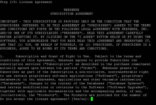
The protector software is provided on an ISO image. Download the image, WebsenseDataSecurityProtector77x.iso, from MyWebsense and burn it to a CD.
|
|
d.
|
An installer page appears. If you are using a regular keyboard and screen, type kvm and press Enter. If you are using a serial console, press Enter. The machine is automatically restarted.
|
|
2.
|
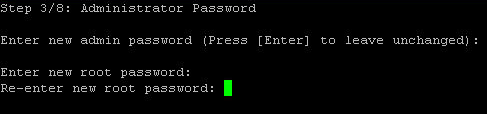
You're prompted to enter a user name and password. Enter admin for both.
|
|
3.
|
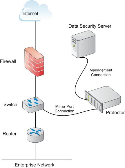
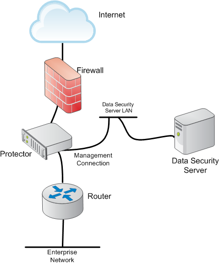
You have the option to install the Websense protector software or mobile agent software. Type P for Protector. Choose this mode whether you are deploying the protector inline or in a SPAN/mirror port configuration. For more information on deploying the protector inline, see Deploying in inline configuration. For more information on deploying the protector in a SPAN/mirror port configuration, see Deploying in SPAN/mirror port configuration.
|
|
1.
|
Enter a number 0-60 to indicate how long (in seconds) you'd like traffic simulated or press Enter to skip this step.
|
|
2.
|


|
2.
|
Select Settings > Deployment > System Modules.
|
|
4.
|
In the Edit Protector dialog, select the Networking tab.
|
|
5.
|
|
6.
|
Select the check box labeled, Enable bypass mode.
|
|
7.
|
Select Force bypass.
|
|
8.
|
Click OK twice.
|
|
9.
|
Click Deploy.
|
|
|
|
|
Installing Data Security Components > Protector
|