Getting Started Guide
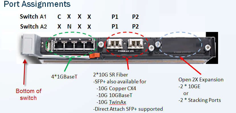
Websense X10G Appliance v7.6.4


1.
Note that the 2 on-chassis switches are oriented vertically at the back of the chassis. The switch on the left side is switch A1. The bottom of the switch is shown at the left in the diagram below. Use an SFP+ cable to connect the P1 interface on chassis switch A1 (left switch) to your network, or install an optical transceiver and then substitute your own fiber optic cable if desired (see details below).
*
Fiber optics: If you ordered an optical transceiver kit with your chassis, follow the instructions provided with the Websense X10G checklist to install the transceivers into the switches at the back of the chassis. (For a copy of the instructions, see support.websense.com/x10g.) This allows you to use fiber optic cables to connect the chassis switches to your network. Begin by connecting the P1 interface on switch A1 to your network. The X10G switch requires an LC connector at the end of the optical cable.
*
If you are not using fiber optic cables, no transceiver kit is required. Connect an SFP+ cable (provided) to the P1 interface on switch A1.
2.
Connect a Category 5 network cable (do not use a crossover cable) from the leftmost network port (Gb) of the Chassis Management Controller to a switch on the subdomain where the CMC IP address is located (see photo below).
The Chassis Management Controller (CMC) is located at the back of the chassis at the upper left side. Connect the Gb port to the network.
*
Use the power cables to connect the 4 on-board power supply units (PSUs) at the bottom (back of chassis) to the power outlets on your computer rack.
Power on the chassis at the front (recessed button at the lower left corner below slots 9 and 10). This powers on all blades. Blades can also be turned off and on individually.